A live steam locomotive can have a sound boiler, accurately machined cylinders, and well-fitted driving wheels yet still run poorly if its valve events are wrong. The valve gear determines when pressurized steam reaches each side of the piston, when admission stops, when expansion takes over, and when spent steam can leave the cylinder. For model engineers, this makes valve gear one of the clearest examples of how geometry, timing, machining accuracy, and mechanical condition operate as one system.
Full-size railway history provides useful context for miniature engines. The Science Museum Group preserves a working-scale Walschaerts valve gear model representing locomotive practice from the late nineteenth century. The mechanism remains valuable to model engineering readers because its moving links make steam distribution visible rather than hiding control inside electronics or enclosed machinery.
Steam Admission Starts With Timing
Inside a reciprocating locomotive engine, steam pressure acts on the piston to create linear movement. A connecting rod then transfers that movement to a crank pin on the driving wheel, changing reciprocating motion into rotation.
The valve has another task. It must open the correct steam passage at an appropriate point in the piston stroke and provide an exhaust path for steam that has already done useful work. The sequencing has to remain coordinated with crank position as the wheels rotate.
This explains why valve gear cannot be treated as a collection of rods added around an otherwise complete engine. Its geometry determines valve travel relative to piston travel.
At startup, an engine may need steam admitted through a larger proportion of the piston stroke to develop useful starting effort. Once moving, earlier cutoff can let admitted steam continue expanding after the inlet closes. The mechanical arrangement gives the operator a way to alter that relationship.
These principles appeared in several valve-gear families across railway history. Stephenson and Walschaerts systems used different layouts, yet both addressed the same fundamental problem: controlling admission, exhaust, direction, and cutoff through mechanical relationships tied to wheel position.
Stephenson Gear Shows Why Packaging Matters
One useful surviving example is Japan’s Class 2100-2109 locomotive at the Nippon Institute of Technology Museum. Built by Dübs and Company in England in 1891, the preserved 0-6-2 tank locomotive uses early vertical Stephenson valve gear. The museum describes the arrangement as durable and suitable for high-speed operation, but notes that its size and weight contributed to later displacement by Walschaerts gear.
That history matters to miniature locomotive builders. An engine design is constrained by space between frames, axle positions, cylinder location, boiler clearance, maintenance access, rod movement, and the practical ability to assemble the mechanism.
A design that functions geometrically on paper may become difficult to build or service at smaller scale. Reducing every full-size dimension by the same ratio does not automatically create an equally forgiving mechanism. Pins become smaller, bearing surfaces shrink, manufacturing errors represent a larger share of total movement, and minor play across several joints can accumulate.
For a model engineer inspecting an unfamiliar locomotive, identifying the type of valve gear is only the first step. Condition and setup matter just as much as the historical design family.
Walschaerts Gear Makes Motion Easier To Study
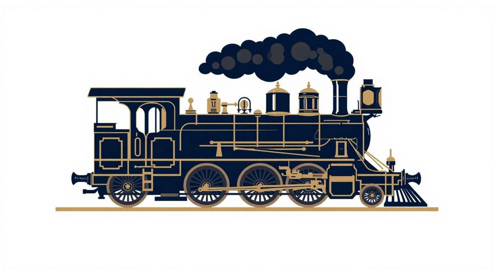
Walschaerts valve gear became one of the most recognizable external mechanisms on steam locomotives. Much of the linkage can be seen beside the driving wheels, making relationships among the crosshead, combination lever, radius rod, expansion link, eccentric crank, and valve spindle easier to observe.
The Science Museum Group holds a demonstration Walschaerts valve gear originating from a London & North Eastern Railway educational collection. Its existence as a teaching model is significant: railway engineers themselves used physical mechanisms to explain motion that can be difficult to understand from static drawings.
That educational value survives in live steam.
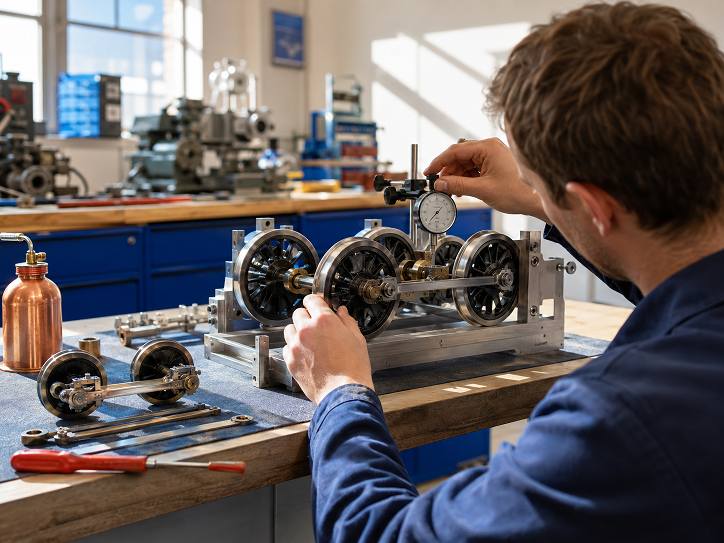
Turning the driving wheels slowly with the locomotive safely cold and secured can make the linkage relationships easier to study. A learner can observe how one movement feeds another and how reversing position changes valve motion. Such observation should remain within established workshop and club safety procedures; boiler-pressure work and adjustments around operating machinery require appropriate experience and supervision.
The wider lesson is useful far beyond steam machinery. Technical choices should be judged through operating history, documented limitations, repeatable behavior, and suitability for the intended use rather than presentation alone. The same comparison habit appears in unrelated consumer fields, including guides evaluating trusted offshore sportsbooks through factors such as operating history, rules clarity, payouts, support, and recurring user feedback. TheRX states that offshore operators sit outside U.S. state regulation, making those checks particularly relevant to its own comparison methodology.
Small Errors Can Become Large Running Problems
Valve gear operates through linked dimensions. Wear or incorrect adjustment at one joint changes what happens farther along the mechanism.
Pin clearance can introduce lost motion. Bush wear can alter effective movement. A slightly incorrect eccentric-crank position can affect the motion transmitted through the gear. Valve-spindle settings influence where admission and exhaust events occur relative to piston position.
That does not mean every imperfect miniature engine needs immediate modification. Diagnosis should begin with observation and documented design information. Changing several variables simultaneously can make the original problem harder to identify.
Model engineers can learn a great deal from preserved full-size locomotives here. The National Railway Museum’s historic drawing collections contain extensive records for valve and reversing gear, including Walschaerts arrangements, eccentric components, reversing shafts, valve-spindle parts, and diagrams for setting valve motion. The records illustrate how railway engineering treated valve gear as a designed assembly with controlled dimensions rather than an approximate linkage.
The same mindset benefits a miniature locomotive workshop. Drawings, measurements, inspection records, and careful comparison provide better evidence than changing parts until the engine appears to improve.
Valve Gear Is Part Of A Larger Engine System
Valve timing cannot compensate for every mechanical problem. A locomotive with restricted steam passages, excessive cylinder leakage, binding rods, poor lubrication, badly aligned axles, or inadequate steam supply can show symptoms that resemble valve-setting problems.
The connecting rod deserves equal attention. The Nippon Institute of Technology Museum describes the main connecting rod on its preserved Class 2100 locomotive as the component that converts reciprocating piston movement into rotation at the driving wheels. That simple description captures why cylinder behavior and running gear cannot be evaluated independently.
Full-size locomotive development reinforces the systems approach. ASME’s record for Texas & Pacific No. 610 describes the 1927 locomotive as an early example of the “super-power” concept, combining a high-capacity boiler, modern valve gear, and a four-wheel trailing truck. Its importance came from the integration of systems rather than one isolated component.
Miniature locomotives operate on a different scale, but the engineering lesson remains recognizable. Steam generation, steam distribution, cylinder condition, running gear, wheel geometry, lubrication, and operator control all influence how the engine behaves.
Why Valve Gear Remains A Powerful Engineering Lesson
Live steam locomotives give mechanical learners something increasingly uncommon: a control system whose logic can be watched in physical motion.
There is no software layer deciding when the valve moves. Geometry performs the calculation. Crank position, link position, lever movement, and valve travel combine continuously as the locomotive runs.
That visibility is one reason steam locomotive engineering remains useful for workshop education. It connects thermodynamics with kinematics, machining with measurement, and historical engineering with practical diagnosis.
For builders and club members, the strongest approach is not to chase a supposedly perfect setting in isolation. Start with the documented design, examine the entire motion system, identify wear or lost motion, compare observations with drawings, and make changes only within appropriate mechanical and pressure-system safety practices.
A well-running live steam locomotive demonstrates what good mechanical engineering often looks like: many ordinary components maintaining the correct relationships at the correct time. Valve gear makes those relationships visible on every revolution of the driving wheels.
