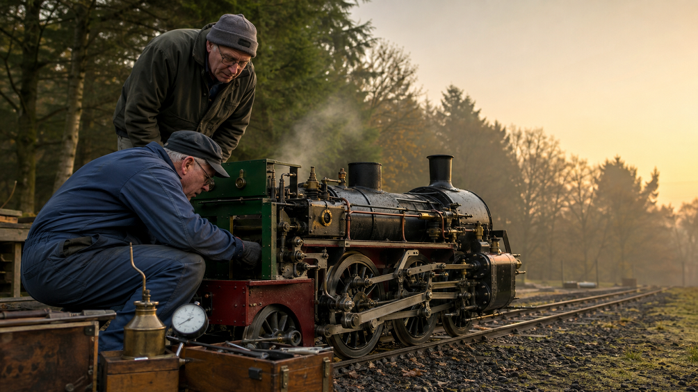
Live steam locomotive engines look compact beside full-size railway machines, yet their basic mechanical logic follows the same chain: heat creates steam, steam pressure acts on pistons, rods transfer movement, and the driving wheels convert reciprocating motion into rotation. For model engineers, that chain is a practical lesson in thermodynamics, valve timing, fit, lubrication, alignment, and safe workshop practice.
A useful way to study these engines is to follow energy flow. The boiler supplies pressurized steam, the cylinders turn that pressure into piston movement, and the running gear turns the stroke into wheel rotation. The National Park Service uses this same sequence in its material on how a steam locomotive works.
The Cylinder Is Where Steam Becomes Mechanical Work
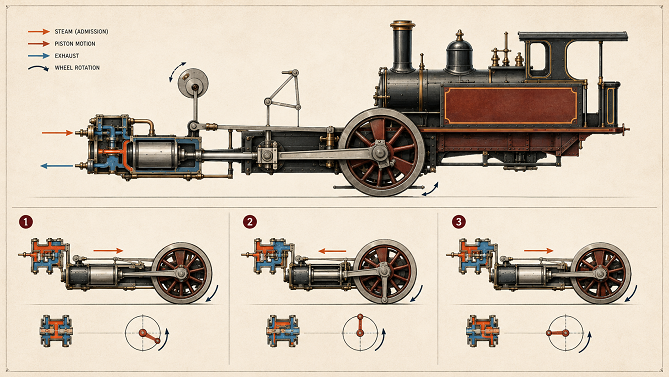
The cylinder is one of the central parts of a reciprocating steam engine. Steam is admitted to one side of a piston, pressure pushes the piston along the bore, and the exhaust path releases spent steam so the cycle can continue. Many locomotive engines use double-acting arrangements, allowing steam to act on alternating sides of the piston during successive strokes.
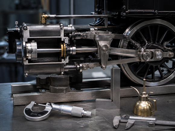
A piston rod carries the force to the crosshead and connecting rod. The connecting rod acts on a crank pin attached to the driving wheel, converting linear movement into rotation.
Scale changes component size, not the importance of fit. Misalignment, excess friction, poor surface finish, or badly matched clearances can waste much of the energy available in a small engine.
Valve Gear Controls When The Engine Can Breathe
Steam pressure alone does not create controlled motion. The engine needs a mechanism that decides when steam enters the cylinder and when exhaust leaves it. That is the job of the valve system and its associated valve gear.
Valve timing affects starting behavior, direction, torque, and steam use. ASME’s history of the Harris-Corliss steam engine shows how admission and exhaust control became a major engineering issue. Locomotive valve gears use different layouts, yet the core question is similar: admit steam at the right point in the piston cycle and release it at the right point afterward.
In a live steam model, valve gear adds educational value. Watching rods, links, eccentrics, and cranks move together makes timing easier to grasp than a diagram alone.
For hobby builders, the visible linkage can reveal the difference between an engine that merely turns and one that runs smoothly across its usable range. Valve travel, lap, lead, and linkage geometry are engineering variables, not decorative details. Studying them at a high level helps explain why two locomotives with similar boilers and cylinders can behave very differently on the track.
Driving Wheels Depend On Geometry, Not Just Torque
A steam locomotive usually has more than one coupled driving wheel. Side rods connect those wheels so they rotate together. The geometry has to stay consistent through a full revolution. If crank positions, rod lengths, axle alignment, or bearing fit are wrong, binding can appear at particular points in the rotation.
Smooth running comes from many small mechanical relationships staying in agreement. Wheel quartering, rod geometry, bearing condition, and lubrication can be as important as the cylinder to how freely the engine rolls.
The same evaluation habit applies to any system with many interacting parts: separate claims from measurable criteria, verify what can be documented, and judge the complete system rather than one attractive feature. That principle can even be seen in unrelated consumer comparisons such as guides on how to pick an online sportsbook, where selection depends on checking concrete factors instead of relying on presentation alone.
Small Steam Engines Make Engineering Visible
Modern engines often hide operation inside castings, controls, sensors, and software. A live steam locomotive exposes much of its mechanical logic: piston rod, crosshead, connecting rod, side rods, drivers, and valve gear.
That visibility makes live steam useful for mechanical education. A learner can see how force changes direction, how rotational and reciprocating motion interact, and how friction or misalignment affects the mechanism.
Safety sets the boundary for hands-on learning. Boilers, pressure vessels, hot surfaces, moving rods, and workshop tools require competent supervision, suitable inspection, and established club or regulatory practices. Educational coverage should never encourage improvised pressure-vessel work or shortcuts around inspection.
Why Engine Quality Is A Systems Question
A good live steam engine is not defined by one polished component. Performance comes from the relationship between steam generation, valve timing, cylinder condition, rod geometry, wheel alignment, lubrication, and operating discipline. Weakness in one area can limit the rest of the machine.
That systems view makes miniature steam locomotives useful to engineering-minded hobbyists. They compress motion, timing, energy conversion, maintenance, and design discipline into a machine small enough to study closely.
