
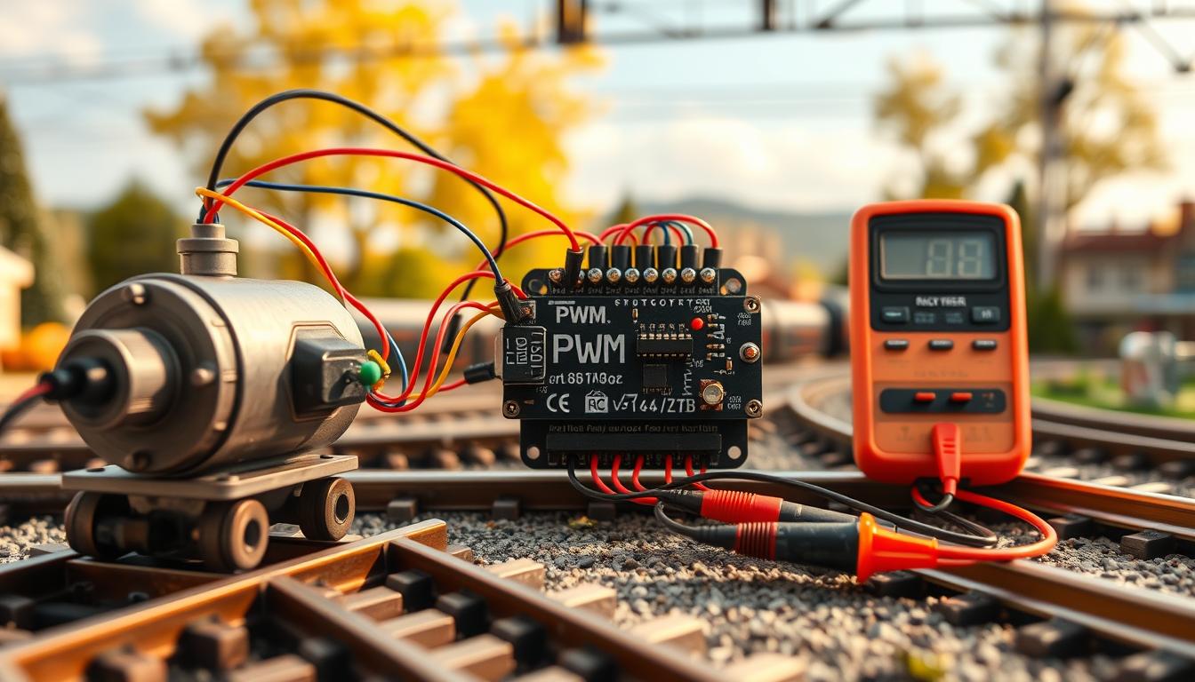
Ever looked at those two rails and wondered how they move tiny trains? I have too. Here’s a secret: model railroading is basically applied physics in a nostalgic package.
The magic comes from DC motor control rules. These rules apply to all, from small N-gauge trains to big ones. Your childhood train set worked on a simple idea. The voltage in the rails controls the model train speed.
Knowing about voltage regulation makes you a better hobbyist. It’s about understanding voltage, current, and resistance. It’s not hard, but it feels good to know.
We’re exploring the electrical basics that make trains move. It’s like getting a backstage pass to the tiny world under the tracks. Whether you use old Lionel or new DCC systems, these principles are always with you.
Ohms law V IR and power P VI sample numbers
Georg Simon Ohm’s discovery in 1827 changed everything. It’s now key in electrical fundamentals and model railroad control systems. His simple equation, V=IR, is at the heart of it all.
Ohm’s law is simple yet powerful. It shows how voltage, current, and resistance are connected. This knowledge helps explain why your controller gets hot or why a switchback won’t work.
Let’s look at some numbers that matter. A typical N-gauge motor uses about 0.15 amps when running smoothly. But, it jumps to 0.8 amps when it hits a buffer.
With 12 volts, the power calculation shows a big difference. It’s 1.8 watts when running well but nearly 10 watts when stalled. That’s a big jump.
Leaving a locomotive against an obstacle can cause trouble. The motor current goes up while the voltage stays the same. This leads to heat, which is not good.
Now, let’s talk about putting a 1-ohm resistor in series with your motor. At 12V and 0.5A, the resistor drops 0.5 volts. This leaves 11.5V for your locomotive. The resistor wastes 0.25 watts as heat, which is energy you could use to move trains.
Adding more locomotives on one controller gets tricky. Current adds up, but your power supply doesn’t. This can lead to problems and frustration when fixing electrical issues.
| Operating Condition | Current Draw (Amps) | Voltage (V) | Power (Watts) |
|---|---|---|---|
| N-gauge cruise | 0.15 | 12 | 1.8 |
| N-gauge stall | 0.8 | 12 | 9.6 |
| HO-gauge cruise | 0.25 | 12 | 3.0 |
| HO-gauge stall | 1.2 | 12 | 14.4 |
Knowing these relationships helps in designing your layout. When planning turnouts and signals, remember each component adds resistance and current. This affects your power budget.
Measuring motor current under different loads is important. It shows if your power supply or controller can handle the load. A 3% grade might seem okay, but if your locomotive can’t handle it, you’ll know.
Too many variables—like multiple units, grades, and tight curves—can cause problems. If your controller shuts down, it’s not just a coincidence. Ohm’s law doesn’t care about your layout dreams or guest schedules.
Build safe battery pack fuse switch current limits
Building a safe power supply is key. It’s about three simple components that cost less than ten dollars. Yet, power supply safety often gets overlooked in model railroading.
Scorch marks on your baseboard can tell a story. They show shortcuts and ignored basics. I’ve learned this the hard way, as have many modelers.
Understanding voltage needs depends on your scale. N-gauge uses 12V, while larger scales need more. Here’s a table to help you figure it out.
| Model Scale | Operating Voltage | Typical Current Draw | Recommended Fuse Rating |
|---|---|---|---|
| N-Gauge | 12V DC | 1-2A continuous | 2-3A fast-blow |
| HO Scale | 14-16V DC | 2-3A continuous | 3-5A fast-blow |
| O Scale | 18-22V DC | 3-5A continuous | 5-7A fast-blow |
| G Scale (Garden) | 20-24V DC | 5-8A continuous | 8-10A fast-blow |
Your fuse should be just above your maximum current draw. This prevents nuisance trips and protects your equipment.
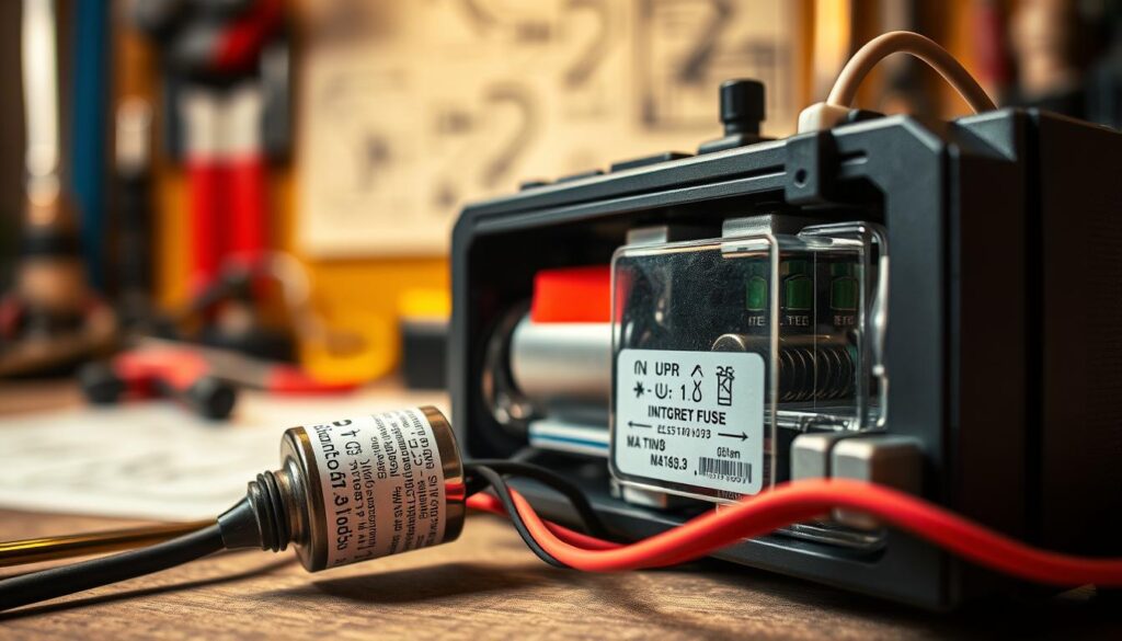
Why fast-blow instead of slow-blow? Fast-blow fuses react quickly to short circuits. They protect wiring before it overheats.
Choosing the right fuse is simple once you know your current usage. Here’s how to keep your power supply safe:
- Measure maximum current during normal operation including accessories and lights
- Add 25% safety margin to account for startup surges and motor stalls
- Select the next standard fuse rating above your calculated value
- Install fuses on both positive and negative leads for extra protection
- Use automotive-style fuse holders that allow tool-free replacement
Don’t forget about the switch. The one from the hardware store is not enough. You need a switch rated for your voltage and at least your fuse rating.
For battery packs, be even more careful. A 12V lithium pack can cause serious damage if shorted. You need:
- Battery management system (BMS) to prevent over-discharge and over-charge conditions
- Fusing on both positive and negative leads rated for short-circuit current
- Polarized connectors to prevent reverse connection
- Wire gauge sized for maximum current, not typical current
- Strain relief at all connection points to prevent fatigue failures
Current limits protect your equipment and you from accidents. They prevent fires and save you from explaining to insurance adjusters.
For portable battery operations, use marine-grade connectors. Anderson Powerpole connectors are a good choice because they’re genderless and rated for high current.
Don’t forget to label your voltage and current ratings on the power supply. This helps you and future you troubleshoot without hassle. Use a label maker or permanent marker.
Murphy’s Law applies to electrical systems. If something can short, it will. Proper protection is not pessimism. It’s planning for reality.
PWM vs variable resistor efficiency low speed smoothness
Ever wondered why your vintage train controller gets so hot? It’s because of the old-school speed control inside. That heat isn’t a cool retro touch. It’s just wasted electricity turned into heat instead of power for your train.
The variable resistor method is like a dimmer switch that wastes power. At half speed, it throws away half of your battery’s energy as heat. It’s simple but not efficient at all.
PWM control is the modern fix that uses electricity like a strobe light. It switches between full and zero voltage fast, making your motor think it’s slower. The best part? You’re not wasting the unused power; you’re just not using it.
The speed control efficiency difference is huge. Old resistor controllers waste 50% or more of your power. PWM control systems lose maybe 5-10% in switching losses. That’s a big difference between a hand warmer and a real speed controller.
But then, the internet forums get loud about motor smoothness at low speeds. PWM at low duty cycles can make cheap motors jerk and stutter. This is because weak magnets in cheap motors don’t handle pulsed power well.
| Control Method | Efficiency Loss | Heat Generation | Low Speed Performance |
|---|---|---|---|
| Variable Resistor | 50-70% | High (requires heat sinks) | Smooth but wasteful |
| PWM (500Hz-1kHz) | 5-10% | Minimal | Audible hum, some jerkiness |
| PWM (15-20kHz) | 5-10% | Minimal | Silent, excellent smoothness |
To fix jerky low-speed issues, don’t ditch pulse width modulation. Use higher frequencies instead. PWM at 15-20kHz is ultrasonic, so only dogs notice. Your motor gets smoother voltage, and you hear nothing.
Some people add small capacitors to smooth out the pulses. Others accept that a cheap locomotive won’t be perfect. Both options are better than spending a lot on cooling a cheap motor.
The best range is 10-90% duty cycle for the best control. Below 10%, most motors struggle. Above 90%, you’re almost at full speed. This range keeps enough AC for track accessories in continuous mode.
The debate between resistors and PWM is like many tech changes. The old way feels familiar but wastes more power. The new way is better but asks you to let go of old habits. Your battery pack doesn’t care about your feelings; it just gets used up faster with more heat.
Modern H-bridge controllers offer PWM control at various frequencies. The hum at lower frequencies is just physics. Raise the frequency above 15kHz, and the hum and energy waste disappear.
Measure current stall vs cruise choose safe controller
The difference between cruise current and stall current is key in controller selection. Motors don’t use a fixed amount of electricity. Their use changes a lot based on what they’re doing.
At motor current, the difference is huge. A small switcher can use a lot of power when it stops moving.
To figure out what your locomotives need, set up your train and measure the current. Use a multimeter in series with the power supply. Watch the numbers closely.
Write down the numbers you see. This is your baseline cruise current. It shows what your locomotive uses when it’s running smoothly.
Now, it’s time to check the stall current. Hold the locomotive so it can’t move and measure again. Emphasis on briefly – you’re creating a short circuit.
The spike you see is your stall current. It shows what happens during derailments or when your train hits an obstacle.
For a typical N-gauge switcher, I measure 0.12-0.18A at cruise and 0.6-1.0A when stalled. That’s a big difference. HO gauge might show 0.3A cruise and 1.5A stall.
The numbers tell a story. Multiply by how many trains you plan to run. Current adds up when powering multiple trains.
Add a 50% safety margin to your total. This buffer covers for surges, tolerances, and real-world conditions.
| Train Scale | Typical Cruise Current | Typical Stall Current | Recommended Controller Rating |
|---|---|---|---|
| N-Gauge (Single) | 0.12-0.18A | 0.6-1.0A | 1.5A minimum |
| HO-Gauge (Single) | 0.25-0.35A | 1.2-1.8A | 2.5A minimum |
| N-Gauge (Three Trains) | 0.36-0.54A | 1.8-3.0A | 4.5A minimum |
| HO-Gauge (Two Trains) | 0.50-0.70A | 2.4-3.6A | 5.0A minimum |
A TIP120 Darlington transistor can handle 5A continuous with proper cooling. It’s good for several small trains or a couple of larger ones. Modern H-bridge modules have both continuous and peak current ratings.
Look at both numbers. Continuous is for long-term use without overheating. Peak is for brief surges.
Also, check if the amperage rating needs cooling or heatsinking. Marketing often shows best-case numbers that are hard to achieve.
Online forums are full of stories about “defective” controllers. They were really just meeting reality. It’s about thermodynamics, not defects.
If your need is near a controller’s max rating, keep shopping. Components work best at 60-70% of their max. Running them harder tests their lifespan.
One last thing: measure your locomotives, not just trust specs. I’ve seen the same model vary by 25% in motor current. Quality control in model railroading can be hit-or-miss.
Math doesn’t bend, and neither does stall current when something unexpected happens. Measure twice, spec generously, and your controllers will last longer than your hobby.
Heat math resistor transistor dissipation heat sink sizing
Every watt not used by your motor turns into heat. It’s important to know how to manage this heat. This isn’t just about keeping things cool; it’s about keeping your electronics working right.
The math for power dissipation is simple. For resistors, P=I²R shows how much heat is made. So, if you have a resistor limiting current, know its heat output.
Take a 1-ohm resistor carrying 0.5 amperes. The math shows P=0.5²×1=0.25 watts of pure heat generation. This might seem small, but check the resistor’s power rating.
Quarter-watt resistors are at their limit. Half-watt is safer. Calculating resistor heat is key to keeping things running smoothly.

Transistors in linear mode are harder to cool. A TIP120 controlling current also heats up. Dropping 5 volts at 0.5 amperes means 2.5 watts of heat inside the TO-220 package.
Without a heatsink, transistors get too hot. The specs warn about thermal limits. A TO-220 package can get up to 62°C/W without cooling.
At 2.5 watts power dissipation, the temperature rise is 155°C. Add room temperature, and you hit 180°C. This is not safe for your components.
The heatsink calculation saves us from overheating. We need (Tjunction – Tambient) / Power = total thermal resistance. For 150°C max junction, 25°C ambient, and 2.5 watts, we need 50°C/W total thermal resistance.
Subtract the junction-to-case resistance—about 1.5°C/W for TO-220 packages—and you need roughly 48°C/W case-to-ambient capability. This is doable with a small aluminum heatsink and the right thermal paste.
| Component Type | Thermal Resistance (°C/W) | Power Handling (2.5W) | Heatsink Required |
|---|---|---|---|
| TO-220 bare package | 62°C/W junction-to-ambient | 155°C rise—fails | Absolutely necessary |
| Small aluminum clip-on | ~25°C/W case-to-ambient | 66°C rise—marginal | Minimum acceptable |
| Medium finned heatsink | ~10°C/W case-to-ambient | 29°C rise—comfortable | Recommended solution |
| Large compound heatsink | ~5°C/W case-to-ambient | 16°C rise—excellent | Professional approach |
PWM control is more efficient. Switching mode transistors only lose power during quick on/off cycles. This reduces heat dissipation to almost nothing.
Linear control versus PWM is a big difference. PWM might need no heatsink, while variable resistors do. This is physics at work, favoring smart design.
Managing heat is more than math; it’s about testing. Check your components’ temperature. If it’s too hot, your heatsink or duty cycle needs adjusting.
Monitoring temperature during testing is wise. Components near thermal limits age fast, work poorly, and fail suddenly. Having enough thermal headroom is cheap insurance against these problems.
EMI noise ferrite beads twisted pairs tidy wiring
Every modern model railroad faces invisible electromagnetic gremlins. But, you can fight them with simple fixes. Digital control systems, DCC decoders, and Arduino sensors all face a common enemy: electromagnetic interference.
This interference can make your locomotive ignore “stop” commands. It’s like it’s not listening.
PWM controllers and DC motors are the main culprits of electrical noise. PWM switching creates sharp voltage changes that send out electromagnetic fields. Motor brushes also add to the noise, sparking like tiny lightning storms.
These sources of electromagnetic interference can mess with your wiring. They can make your Hall effect sensor trigger false signals. Your DCC decoder might think “forward” means something different than you do.

Ferrite beads are a first defense against high-frequency interference. They act like frequency-dependent resistors, blocking RF noise while letting DC and low-frequency signals pass. The ferrite material turns high-frequency electromagnetic energy into heat.
Put ferrite beads on motor leads, one on each wire close to the motor. This stops noise before it spreads through your wiring. Quality beads cost about fifty cents each and can cut motor noise by 80-90%.
The right impedance matters more than size. Look for beads with 100 to 1000 ohms at 100MHz for model railroads. Higher impedance means better noise suppression, but it doesn’t help much above 1000 ohms.
Twisted pair wiring uses a clever trick to cancel out electromagnetic fields. When two wires twist together, any external field induces equal voltages in each wire. These voltages cancel out at the end, rejecting common-mode noise.
This method is why network cables and professional audio systems use twisted pair wiring. For your track bus and power distribution, twist wires at three to four turns per inch. The exact number is less important than keeping it consistent.
Keeping different circuit types apart prevents electrical noise from spreading. Keep high-current wiring at least four inches from low-voltage wiring. When paths cross, make sure they intersect at 90-degree angles to reduce magnetic coupling.
Grounding is key to avoiding hum or buzz on your layout. Multiple ground paths can create ground loops, causing problems. Star grounding fixes this by having all grounds return to one point.
| EMI Mitigation Technique | Effectiveness | Cost Per Application | Installation Difficulty |
|---|---|---|---|
| Ferrite beads on motor leads | 80-90% motor noise reduction | $0.50-$2.00 | Simple clip-on installation |
| Twisted pair power wiring | 60-75% conducted noise reduction | $0.10-$0.30 per foot | Moderate—twist during installation |
| Shielded cable for sensors | 70-85% radiated noise immunity | $0.50-$1.50 per foot | Moderate—requires proper grounding |
| Star grounding topology | Eliminates ground loop interference | Minimal wire cost | Complex—requires layout planning |
Shielded cable protects analog sensor signals near PWM controllers or motor wiring. The shield catches radiated fields before they cause noise. Ground the shield at one end only to avoid ground loops.
Is this engineering overkill for a simple DC layout? Maybe at first. But add DCC operations, block occupancy detection, automated signaling, and computer control, and you’ll face more complex issues. The 20kHz hash from PWM switching can mess with sensor wiring, causing false triggers.
Professional practical shielding and EMI noise reduction techniques work for model railroads and industrial systems. The physics is the same, whether you’re controlling a G-scale outdoor railroad or protecting medical equipment.
Tidy wiring is not just about looks; it’s about electrical hygiene. Keep power and signal cables separate. Use cable ties to keep runs organized and prevent changes in coupling characteristics over time. Label everything because you won’t remember which twisted pair goes where later.
Investing in proper noise suppression techniques pays off in system reliability and less troubleshooting time. Spend an afternoon on ferrite beads, twisted pairs, and star grounding now, or spend dozens of frustrating hours later. Trust me, I’ve been there—after I’ve had coffee.
Extension speedometer with Hall sensor and Arduino
Measuring how fast trains move is simple with a magnet, a sensor, and some curiosity. Want to know for sure how fast your trains go? Welcome to digital sensing. Here, a Hall effect sensor and Arduino turn your railroad into a lab. It’s like something out of Victorian times.
Just put a tiny magnet on a train wheel or axle. Place a Hall effect sensor near where the magnet goes by.
When the magnet passes, the sensor detects the magnetic field and sends a digital signal. Arduino counts these signals, tracks time, and figures out the speed.
Now, you have real numbers instead of guesses. It’s not necessary, but it’s very satisfying to know the exact speed.
Sensor Selection and Mounting
There are many Hall effect sensor options like the A3144, SS49E, and others. They’re cheap and work well at close range.
Mount the sensor on your train or track, 1-3mm from the magnet. This gives strong signals but leaves room for movement.
Use one magnet per wheel for easy math. More magnets mean more detail but harder math.
Wiring and Arduino Connection
Connecting the sensor is easy. Most need power, ground, and a signal output.
Connect the signal to an Arduino pin that can handle interrupts. Pins 2 and 3 on Arduino Uno work great.
If your sensor needs a pull-up resistor, use one. Arduino’s internal pull-up works for most.
- Red wire: Connect to Arduino 5V pin
- Black wire: Connect to Arduino GND pin
- Yellow/Signal wire: Connect to Arduino digital pin 2 or 3
Code Implementation
Arduino speed measurement uses interrupts and time tracking. Set up an interrupt on your chosen pin for rising edges.
The interrupt routine just counts pulses. In the main loop, use millis() to track time and calculate speed.
This method counts pulses accurately, even while doing other tasks. Speed calculations happen at set intervals.
Speed Calculation Mathematics
To get speed from pulse counts, do some math. First, find RPM: (pulse_count / magnets_per_revolution) × (60000 / elapsed_milliseconds).
Then, convert RPM to scale speed. Know your wheel size and scale ratio. For HO scale, use a specific formula to convert.
The formula is: Scale_MPH = (RPM × Wheel_Circumference_Inches × 60 × Scale_Ratio) / (12 × 5280). Use a constant for your setup to make calculations easier.
Practical Applications
Basic speed measurement is just the start. Log speed data for later analysis. See how speed changes in different parts of your layout.
Use sensors for train position and speed control. This makes trains run smoothly together. It’s like having a model train cruise control.
Even more, you can control speed in rail yards or speed limits. It’s like having a model train speed camera.
Sensor Comparison Table
| Sensor Model | Output Type | Operating Voltage | Sensing Range | Typical Cost |
|---|---|---|---|---|
| A3144 | Digital (latching) | 4.5-24V | 0-3mm | $0.50-$1.00 |
| SS49E | Analog (linear) | 3-6.5V | 0-5mm | $1.00-$2.00 |
| US5881 | Digital (latching) | 3.5-30V | 0-4mm | $0.75-$1.50 |
| AH3503 | Digital (switch) | 2.5-5.5V | 0-2mm | $0.60-$1.20 |
Advanced Implementation Notes
For those who love data, send speed data over serial for real-time graphs. Show how trains speed up, stay steady, and slow down.
Track how voltage drops affect speed in different parts of your layout. Compare theoretical speeds with real ones.
This shows real-world losses and efficiency. It’s a detailed look at how things really work, not just theory.
Is this needed for just running trains? No. But it’s fun and useful for those who enjoy tinkering. It’s a way to make your hobby more interesting.
Plus, knowing the exact speed is satisfying. It’s like solving a puzzle, and it keeps you up late at night.
Safety low voltage fusing insulation storage
Many modelers learn the hard way: low voltage systems can turn your hobby space into an expensive lesson. The idea that 12 volts can’t cause problems? That’s the kind of thinking that leads to conversations with homeowner’s insurance adjusters.
You won’t get shocked by grabbing bare 12V rails, true. But electrical safety at low voltages concerns different hazards. When 12 volts pushes 10 amps through inadequate wiring, you’ve created a resistive heating element that doesn’t respect your voltage-based complacency.
Short circuits at these levels generate enough current to start fires or melt expensive equipment in seconds.
Fusing Your Layout Properly
Every power supply output needs appropriate fuse protection before reaching your layout. This isn’t optional safety theater—it’s your first defense against catastrophic failures. Automotive blade fuses work beautifully for model railroad applications and come in every current rating you’ll need.
Match fuse ratings to both wire gauge and expected load. A 5-amp fuse on a 3-amp circuit provides headroom without leaving dangerous gaps in protection.
Wire gauge becomes critical for low voltage safety because of resistance. A 20-foot run of 24-gauge wire carries about 0.5 ohms of resistance. At 2 amps, that’s a 1-volt drop and 2 watts of heating. Double the current, and you’ve quadrupled the dissipation—remember P=I²R from earlier sections.
Use these gauge recommendations for reliable operation:
- 18-gauge wire for main track buses and primary power distribution
- 20-gauge wire for branch circuits and accessory feeders
- 22-gauge wire for individual turnout motors and lighting
- Never trust the thin wires included with cheap power supplies—they’re optimistic fiction
Insulation Quality and Inspection
Quality wire insulation separates layouts that last decades from those that short circuit eventually. Modern silicone-insulated wire resists heat and abrasion far better than standard PVC insulation. The extra cost per foot pays for itself in longevity and peace of mind.
Check your wiring annually for damage, specially where wires move, flex, or pass through tight spaces. Cracked insulation is a fire waiting for the right excuse.
Inspect connections at terminal blocks and solder joints for signs of overheating—discoloration means something got too hot.
Battery Storage Done Right
Battery-powered operations demand special attention to safe storage practices. Lithium cells can vent, swell, or in extreme cases combust if damaged, overcharged, or stored in hot environments. These aren’t theoretical risks—they’re documented failure modes.
Follow these protocols for battery safety:
- Store batteries at 40-60% charge in cool, dry locations away from flammable materials
- Use fireproof charging bags if you’re particular cautious (and you should be)
- Never leave charging batteries unattended—yes, this is tedious; rebuilding your layout after a fire is more so
- Inspect batteries regularly for swelling, damage, or unusual warmth
- Dispose of damaged cells properly through designated recycling programs
Polarized connectors prevent reverse-polarity accidents that release magic smoke. Anderson Powerpoles have become popular in the hobby because they’re nearly impossible to connect backward and they handle realistic current loads without overheating.
Labeling and Organization
Label everything: voltage, polarity, current rating. Future you—or your confused friend helping with the layout—will appreciate not having to trace mystery wires with a multimeter at 11 PM. Clear labeling is one of those electrical safety practices that seems excessive until you need it.
Use consistent color coding throughout your layout. Red for positive, black for negative, and stick to it religiously.
| Safety Component | Recommended Specification | Common Failure Point | Prevention Method |
|---|---|---|---|
| Circuit Fuses | 20% above normal operating current | Undersized for actual load | Measure stall current, size according |
| Power Wire Gauge | 18 AWG for buses, 20-22 AWG for branches | Voltage drop causing heating | Calculate resistance over run length |
| Battery Storage | 40-60% charge in fireproof container | Full charge in hot environment | Use LiPo storage mode, cool location |
| Connector Type | Polarized, rated for 150% peak current | Reverse polarity connection | Anderson Powerpoles or equivalent keyed connectors |
Safety isn’t the exciting part of this hobby, I’ll grant you that. But it’s the foundation that allows all the exciting parts to continue existing. Proper fuse protection, adequate wire insulation, and intelligent safe storage practices aren’t about paranoia—they’re about probability management.
You’re working with enough current to cause real damage. Respect that reality, and your layout will provide decades of enjoyment instead of becoming an expensive cautionary tale.
Circuit diagrams and parts list
Theory ends where soldering begins. Your bill of materials is simple. You need a 12V power supply, an Arduino Nano, and a TIP120 Darlington transistor or IRLZ44N MOSFET. Also, a 1N4001 flyback diode, a 1k-ohm base resistor, and a heatsink.
For bidirectional control, consider an L298N H-bridge module. It’s affordable and handles 2A continuous per channel. Your wiring diagram will be easy: Arduino PWM to the enable pin, and two digital outputs for direction.
Choosing the right components is key. Use terminal strips for connections and inline fuse holders for protection. Anderson Powerpole connectors are good for high current, while JST or Dupont connectors work for signals. Remember, 18 AWG wire is for power and 22 AWG for control signals.
Document your wiring before it becomes a mystery. Take photos and draw schematics. Use a label maker or Sharpie on masking tape. This way, your circuit diagram will help you troubleshoot later. I’ve been there, wondering about the chaos, only to find the solution in old notes.
